After unpacking the instrument carefully, we recommend to check the package contents and inspect for breakage. In the table lists the package contents of the RRDE-3A. This list is subject to change the parts. It is strongly recommended to refer to the packing slip with your instrument. Assemblies of these various parts will be outlined in the following chapters. The shipping box and packing materials retain until you have fully tested the unit to be certain that no damage was incurred during shipping. If a shortage exists, you should contact with local distributor or ALS Customer Service and describe the shortage. A replacement part will be sent immediately subject to stock availability.
| Catalog No. | Description | Quantity |
| 012623 | RRDE-3A Rotating Ring Disk Electrode Apparatus | 1 |
| 012632 | RRDE-3A glass cell vial 100 mL | 1 |
| 012064 | Spin coating adapter | 1 |
| 012065 | Male connector for gas purge (PP) | 1 |
| 013392 | TYGON tubing, OD1/4 x ID1/8 | 1 |
| 013271 | RRDE-3A Teflon cap V.2 | 1 |
| 012642 | RRDE-3A Silicon sheet 100x180mm | 1 |
| O-ring for RRDE-3A Bearing assembly | 3 | |
| O-ring for RRDE-3A Shaft assembly | 3 | |
| Instruction manual | 1 | |
| Power cable | 1 | |
| Optional Products | ||
| 012074 | CB-ES Remote cable | 1 |
| 009131 | Port plug | 1 |
| 012961 | Platinum counter electrode 23cm | 1 |
The RRDE-3A is adopted to either 100 or 220 V (50-60 Hz) power supply. As power
switching regulator has been setting in the instrument, switching of the
electricity is automatically controlled.
Push the socketed end of the power cord into the port located in the back-panel
(See Fig. 2-1). After making this connection, make certain the power ON/OFF
switch is in the certain position. This switch is labeled with a “O” and “|”.
When in “O”position, the power is OFF and when in “|”, the power is ON.


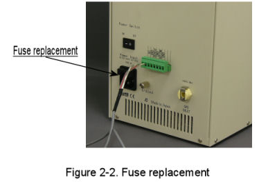
The fuse is located on the power cord connector. Pull fuse holder, and check
whether it works or not. If it does not work, it should be replaced with new
one. (Fig. 2-2)
The RRDE-3A gas purge and rotator speed are controlled by the the potentiostats with TTL control function. The control line is 2 pin cable between the remote terminal on the rear of the RRDE-3A and the cell control on the rear panel of the potentiostat.
The electrode leads are connected to the potentiostat on the end of the cell lead cable into the Electrodes female connector on the rear panel of the potentiostat.

(Fig. 2-3)
Push the socketed end of the power cord into the port located in the RRDE-3 back
panel. Before making this connection, always make sure that the power ON/OFF
switch is in the "OFF" position. This switch is labeled with a "O" and "|" .
When "O" is pushed, the power is "OFF" and when "|" is pushed, the power is
"ON".
Three cables are required to connect the RRDE-3A to the potentiostat. Electrode
rotation can be automatically turned ON or OFF by TTL control. The control line
is a cable between the remote terminal on the back of the RRDE-3A and the GND
and RDE on the back of the potentiostat (See Fig. 3-1).
In order to control purging remotely, the purge cable should be connected to
remote terminal on the back of the RRDE-3A (Fig. 2-3; Fig. 3-1).
Since the cable controls the electrode rotation, the other end of this cable should be connected to the remote port on the back of the potentiostat (See Fig. 3-1).