3. Connection of RRDE-3A and Potentiostat

-
RRDE-3A control:
In case of RRDE-3A works with CHI or BASi apparatus, a banana
plug cable is connected with the RDE and GND, and the alternative
cable is connected with the terminal connector and GND of the
RRDE-3A.
One volt corresponds to 1,000 rpm, and it is possible to control 90
to 8,000 rpm from 0 to 8 DC volts. The rotation speed from the 90 to
8,000 rpm can be controlled in order to the specification of the
RRDE-3A rotator.
The purge and pintch valve into RRDE-3A is controlled by TTL level
Active Low. The signal from MOTOR/GND stops the motor on the REMOTE
or LOCAL mode.
-
RRDE-3A to Non-ALS Instruments:
The RRDE-3A should work, at least in the manual mode, with
virtually any instrument. The CELL cable is attaching the
appropriate connector for the particular instrument.
-
Electrode leads:

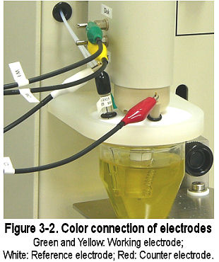
The reference and counter electrodes lead wires extend from the potentiostats. The connectors are the press-on type. Simply push the connector over the corresponding pin in the electrode to make the connection (Fig. 3-2). Aligator clips are color coded to the electrode which it attaches.
-
Gas inlet connection:

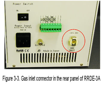
The RRDE-3A includes 0.25" O.D. tygon tube and a gas line
fitting. One end of the fitting connects to the ‘GAS INLET’ port on
the rear panel of the RRDE-3A. To attach the line, simply push the
connector (See Fig. 3-3). The open end of the tygon tube is
connected to a regulated gas supply. The inlet gas pressure must not
exceed 5 psi.
To remove the tube from RRDE-3A, squeeze the retaining ring tab
against the connector and then pull the tube and connector away from
the RRDE-3A.
-
Cell and electrodes setting:
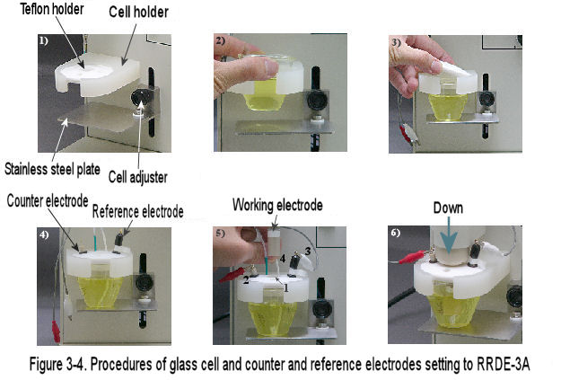
RRDE-3A is designed for easy cell replacement and to accommodate
regular cells. The cell is held in place by stainless steel plate.
These instructions should be followed for initial cell setting:
1) Schematic of the cell holder.
2) A glass cell vial separately keeps at the cell holder. Rotate
stainless steel plate at left under the cell holder.
3) The glass cell vial is put on the stainless steel plate, and put
the teflon cap on the cell holder.
4) Adjust its stainless steel plate height to fit between glass cell
and cell holder, and cell vials is fixed at the cell holder.
5) Three 0.25" holes are situated in the teflon cap (Fig. 3-4-5).
These holes are for reference, counter electrodes, and other. Place
the electrodes which are the most convenient.
6) Sliding reference and counter electrodes are adjust the desired
position by O-ring.

-
Purge line connection:
The RRDE-3A has the ability to purge the sample solution with an
inert gas. The purge removes oxygen by bubbling with an inert gas,
typically Nitrogen or Helium through the solution.
The purge line consists of a teflon tube emmerging from the teflon
cap.
This line should be set up to the down side of the cell holder. The
depth of the purge tube should be near the bottom of the cell vial.
In order to access the purge tube when RRDE-3A is lowered, you
should prepare for adjusted length of the tube.