4. Motor and working electrode assemblies
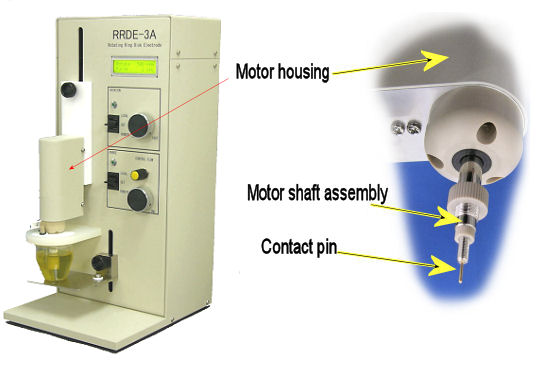
After motor cable is removed from motor shaft assembly and motor connector, cell leads are released from counter and reference electrodes. Motor shaft assembly is turned counterclockwise, and then disassembled from the RRDE-3A. Since the top of the contact pin for RRDE-3A is very sharp, an appropriate rotating ring disk electrode (RRDE) should be carefully attached on the shaft assembly.

Therefore, stainless steel cell holder is pulled out very gently,
being careful not to hit the contact pin or working electrode. Since
the PEEK body of the working electrode is held by finger, screw is
turned counterclockwise by finger, and the working electrode is
removed from the shaft. It is of major importance that contact pin
is touched to the part of the working electrode electrically. When
working electrode is assembled with motor shaft, an O-ring should be
attached between the working electrode and the shaft to protect
corrosion due to acidic or basic electrolyte. Then the assembly
needs to contact to the ground. All lines are Active Low.
The following operational instructions are given under “Initial
instrument operation” (Chapter 5) to remote rotation.
-
Gas purge:
The LED is flashing when the purge function is ON, either
remotely or manually. To control purge remotely, the purge and
rotating remote cable are connected on the back panel of the
RRDE-3A. Time of the purging is controlled manually or via TTL
control by the potentiostats software.
Do not use Hydrogen gas as purge,
because teflon tubing is used for gas flow, and small molecule such
as hydrogen is penetrated from the teflon tubing. Hydrogen gas has
possibility to leak from the teflon tubing. Please use inert gas
such as Nitrogen or Helium gas as purge purpose
- General instructions:
The power switch on the back panel should be "OFF" position. The motor shaft assembly is then connected to the main body with the motor cable. The main power connection must have proper grounding.
-
Warning:
Any disconnection of the ground wire either inside or outside the instrument may be dangerous. DO NOT DISCONNECT.
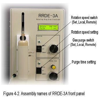
Make sure that the motor shaft assembly is mounted on the cell holder with RRDE-3A, and the power switch should be set "Local". When the electrode has been rotated, never try to touch with RRDE shaft. Let the Speed digital switch rotate until the display reading comes approx. 1,000 rpm. Visually inspect the shaft and electrode body during rotation. Then check that the top of the electrode body is connected with the shaft firmly, and stop its rotation by switching to the "Lower speed". The solution should be thoroughly purged before using with the gas purging function on the front panel of the unit. The most effective purging is done by using a low-pressure inert gas source connected to the gas tube on the rear panel. The GAS ADJUST valve controls the rate of purging.
In case of RRDE electrode is used,
please check its rotation speed. Max rotation speed does not exceed
over 3,000 rpm due to electrode damage.
In case of RDE electrode is used, please
check its rotation speed. Max rotation speed does not exceed over
7,000 rpm due to electrode damage.
