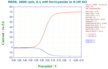
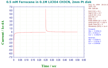
Overview
The Model 700E series are computerized general-purpose
potentiostat / bipotentiostat / galvanostat instruments. A
typical application involves a rotating ring-disk electrode
(RRDE), but these systems can also be used for other
applications where dual channel measurements are essential,
such as dual channel electrochemical detection. The system
contains a fast digital function generator, a direct digital
synthesizer for high frequency ac waveforms, high speed dual
channel data acquisition circuitry, (bi)potentiostat, and a
galvanostat (only available in select models). The potential
control range is ±10 V and the current range is ±250 mA. The
instrument is capable of measuring current down to tens of
picoamperes. The steady state current of a 10 μm disk
electrode can be readily measured without external adapters.
With the CHI200B Picoamp Booster and Faraday Cage (fully
automatic and compatible with the 700E series), currents
down to 1 pA can be measured (primary current channel only).
These instruments are very fast. The function generator can
update at a 10 MHz rate. Two high speed and high resolution
data acquisition channels allow both current channels or
current and potential (or external voltage signal) to be
sampled simultaneously at 1 MHz rate at 16-bit resolution.
The instrument provides a very wide dynamic range on
experimental time scales. For instance, the scan rate in
cyclic voltammetry can be up to 1000 V/s with a 0.1 mV
potential increment or 5000 V/s with a 1 mV potential
increment. The potentiostat / galvanostat uses a 4-electrode
configuration, allowing it to be used for liquid/liquid
interface measurements and eliminating the effect of the
contact resistance of connectors and relays for high current
measurements. The data acquisition systems allow an external
input signal (such as spectroscopy signals to be recorded
simultaneously with electrochemical data). The instrument
will also automatically re-zero both potential and current,
so that periodic re-calibration of the instrument can be
avoided.
The 700E series shares many common features with the 600E
series. When used as a single channel potentiostat, the
instrument is identical to the model 600E series. The
bipotentiostat is realized by adding the second channel
potential control and current measurement board to the model
600E series. There are also two filter stages, three extra
gain stages, and channel selection circuitry on the board.
When it is used as a bipotentiostat, the second channel can
be controlled at an independent constant potential or to
scan/step at the same potential as the first channel. In
case of CV, it can also scan with a constant potential
difference with the first channel. Techniques available for
the second channel include CV, LSV, SCV, CA, DPV, NPV, SWV,
and i-t.
The 700E series is the upgrade to our very popular
700/700A/700B/700C/700D series. The major improvements of
this series are very stable and accurate potential and
current control, and dual channel data acquisition at high
speed.
The 700E series has a USB port (default) and a serial
port for data communication with the PC. You can select
either USB or serial (but not both) by changing a switch
setting on the rear panel of the instrument.
The 700E series also has a true integrator for
chronocoulometry.
Two 16-bit highly stable bias circuits are used for
current and potential bias, allowing wider dynamic range in
AC measurements. These can also be used to re-zero the DC
current output.
The instrument is capable of a wide variety of
electrochemical techniques, and is available with integrated
simulation and fitting software functions for both impedance
and cyclic voltammetry. These features provide powerful
tools for both electrochemical mechanistic studies and trace
analysis.
We provide several different models in the 700E series.
The model comparison table compares the different models.
Other than what is listed, the specifications and features
of these models are identical. Models 700E and 710E are
basic units for mechanistic study and electrochemical
analysis, respectively. Models 720E and 730E are
comprehensive electrochemical analyzers. Model 750E and 760E
are advanced electrochemical workstations.

