-
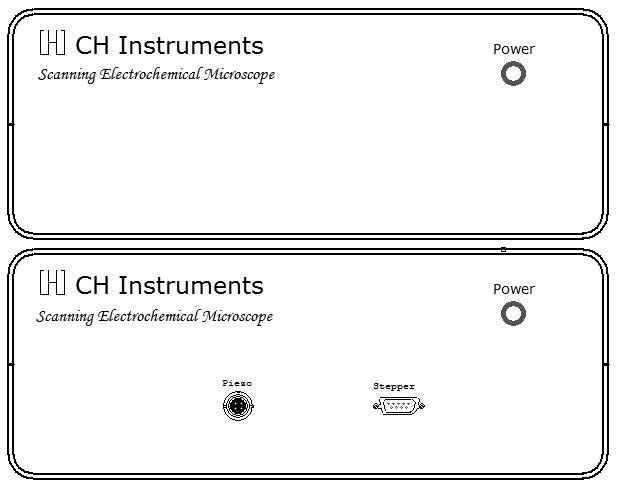
Nanopositioner
-
X, Y, Z resolution: 1.6 nm with Piezo positioner,
closed loop control, 8 nm with stepper motor
positioner
-
X, Y, Z total distance: 50 mm
-
Potentiostat / Bipotentiostat
- Zero resistance ammeter
- 2- or 3- or 4-electrode configuration
- Floating (isolated from earth) or earth
ground
- Maximum potential: ±10 V for both
channels
- Maximum current: ±250 mA continuous (sum
of two current channels), ±350 mA peak
- Compliance Voltage: ±13 V
- Potentiostat rise time: < 1 μs, 0.8 μs
typical
- Applied potential ranges (volts): ±0.01,
±0.05, ±0.1, ±0.65, ±3.276, ±6.553, ±10
- Applied potential resolution: 0.0015% of
potential range
- Applied potential accuracy: ±1 mV,
±0.01% of scale
- Applied potential noise: < 10 μV rms
- Measured current range: ±10 pA to ±0.25
A in 12 ranges
- Measured current resolution: 0.0015% of
current range, minimum 0.3 fA
- Current measurement accuracy: 0.2% if
current range >=1e-6 A/V, 1% otherwise
- Input bias current: < 20 pA
-
Galvanostat
- Galvanostat applied current range: 3 nA
- 250 mA
- Applied current accuracy: 20 pA ±0.2% if
> 3e-7A, ±1% otherwise
- Applied current resolution: 0.03% of
applied current range
- Measured potential range (volts):
±0.025, ±0.1, ±0.25, ±1, ±2.5, ±10
- Measured potential resolution: 0.0015%
of measured range
-
Electrometer
- Reference electrode input impedance:
1x10¹² ohm
- Reference electrode input bandwidth: 10
MHz
- Reference electrode input bias current:
<= 10 pA @ 25°C
-
Waveform Generation and Data Acquisition
- Fast waveform update: 10 MHz @ 16-bit
- Fast data acquisition: dual channel
16-bit ADC, 1,000,000 samples/sec
simultaneously
- External signal recording channel at
maximum 1 MHz sampling rate
-
Other Features
- Automatic and manual iR compensation
- Current measurement bias: full range
with 16-bit resolution, 0.003% accuracy
- Potential measurement bias: ±10 V with
16-bit resolution, 0.003% accuracy
- External potential input
- Potential and current analog output
- Programmable potential filter cutoff:
1.5 MHz, 150 KHz, 15 KHz, 1.5 KHz, 150 Hz,
15 Hz, 1.5 Hz, 0.15 Hz
- Programmable signal filter cutoff: 1.5
MHz, 150 KHz, 15 KHz, 1.5 KHz, 150 Hz, 15
Hz, 1.5 Hz, 0.15 Hz
- RDE control output (Model 730E and up):
0-10 V (corresponding to 0-10000 rpm),
16-bit, 0.003% accuracy
- Digital input/output lines programmable
through macro command
- Flash memory for quick software update
- Serial port or USB selectable for data
communication
- Cell control: purge, stir, knock
- Maximum data length: 256K-16384K
selectable
- Real Time Absolute and Relative Distance
Display
- Real Time Probe and Substrate Current
Display
- Dual-channel measurements for CV, LSV,
CA, DPV, NPV, SWV, i-t
- CV simulation and fitting program,
user-defined mechanisms
- Impedance simulation and fitting program
|
-
Scanning Probe Techniques
- SECM Imaging (SECM): constant height,
constant current, potentiometric and
impedance modes
- Probe Approach Curves (PAC)
- Probe Scan Curve (PSC): constant height,
constant current, potentiometric, impedance,
and constant impedance modes
- Surface Patterned Conditioning (SPC)
- Surface Interrogation SECM (SISECM)
- Z Probe Constant Current Control
-
Sweep Techniques
- Cyclic Voltammetry (CV)
- Linear Sweep Voltammetry
- Tafel Plot (TAFEL)
-
Step and Pulse Techniques
- Staircase Voltammetry (SCV)
- Chronoamperometry (CA)
- Chronocoulometry (CC)
- Differential Pulse Voltammetry (DPV)
- Normal Pulse Voltammetry (NPV)
- Differential Normal Pulse Voltammetry (DNPV)
- Square Wave Voltammetry
-
AC Techniques
- AC Voltammetry (ACV)
- Second Harmonic AC Voltammetry (SHACV)
- Fourier Transform AC Voltammetry (FTACV)
- AC Impedance (IMP)
- Impedance versus Potential (IMPE)
- Impedance versus Time (IMPT)
-
Galvanostatic Techniques
- Chronopotentiometry (CP)
- Chronopotentiometry with Current Ramp (CPCR)
- Multi-Current Steps
-
Other Techniques
- Amperometric i-t Curve (i-t)
- Differential Pulse Amperometry (DPA)
- Double Differential Pulse Amperometry (DDPA)
- Triple Pulse Amperometry (TPA)
- Integrated Pulse Amperometric Detection
(IPAD)
- Bulk Electrolysis with Coulometry (BE)
- Hydrodynamic Modulation Voltammetry
(HMV)
- Sweep-Step Functions (SSF)
- Multi-Potential Steps (STEP)
- Electrochemical Noise Measurement (ECN)
- Open Circuit Potential - Time (OCPT)
- Various Stripping Voltammetry
- Potentiometry
-
Experimental Parameters
- CV and LSV scan rate: 0.000001 to 10,000
V/s, two channels simultaneously
- Potential increment during scan: 0.1 mV
@ 1,000 V/s
- CA and CC pulse width: 0.0001 to 1000
sec
- CA minimum sample interval: 1 μs, both
channels
- CC minimum sample interval: 1 μs
- True integrator for CC
- DPV and NPV pulse width: 0.001 to 10 sec
- SWV frequency: 1 to 100 kHz
- i-t sample interval: minimum 1 μs, both
channels
- ACV frequency: 0.1 to 10 kHz
- SHACV frequency: 0.1 to 5 kHz
- FTACV frequency: 0.1 to 50 Hz,
simultaneously acquire 1st, 2nd, 3rd, 4th,
5th, and 6th harmonics ACV data
- IMP frequency: 0.00001 to 1 MHz
- IMP amplitude: 0.00001 V to 0.7 V rms
-
2D and 3D Graphics:
- Interactive visualization of SECM
surfaces
- Color mapping
- Laplacian smoothing
- Stereoscopic 3D anaglyph imaging
- High compatibility: Windows 98 and up,
256 colors (VGA) and up, no special video
card or display required
|